Thông tin chi tiết sản phẩm:
|
Tiêu chuẩn: | NFPA 285 | Tên máy: | Thiết bị kiểm tra lan truyền tường bên ngoài bức tường |
---|---|---|---|
Mẫu thử: | Các cụm tường và bảng điều khiển tường không chịu được | Bảo hành: | 12 tháng |
Thời gian giao hàng: | 30 ngày làm việc | Đầu đốt: | 2 |
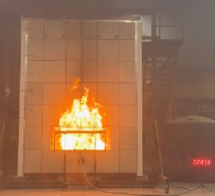
NFPA 285 Exterior Wall Assemblies Fire Propagation Testing Apparatus
Scope
This standard provides a test method for determining the fire propagation characteristics of exterior non-load-bearing wall assemblies and panels used as components of curain wall assemblies, constructed using combustilble materials or that incomorte combusibie components, that ae imended to be installed on buildings required to have exterior walls of noncombustible construction.
The fire propagation characteristics are determined for post-flashover fires of interior origin.
Standard:
NFPA 285 .
Test Facility:
1. The test apparatus described in Section 4.2 shall be located inside a test facility.
2. The test facility shall have minimum dimensions of 30 ft wide x 30 ft deep x 23 ft high (9.1 m x 9.1 m x 7.0 m).
3. The test facility shall have provisions for supplying combustion makeup air taken from the outside during the test
4.The test facility shall be constructed to allow for the exhaust of the combusion by-products during the test while not inducing an airlow on the exterior face of the test specimen.
5. The test facility shall protect the test apparatus and test specimen from exposure to wind and precipitation.
Test Apparatus:
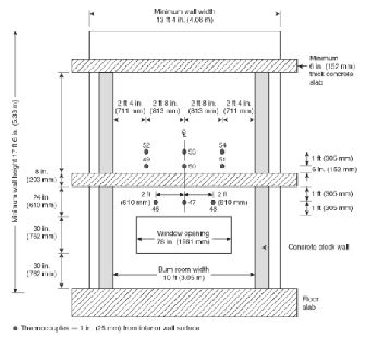
1. The test apparatus shall consist of a two-story structure having a height of 15 ft 8 in. # 1 in. (4.8 m + 25 mm) with a test room on each story.
2. Each testroom shal have uninished inside dimensions of 10 f + 0.5 in. widex 10 ft + 0.5 in.deep(3.05 mt 13 mmx 3.05 mt 13 mm) wih an unfinishedfloor-to-ceiling height of 7 ft± 0.5 in.(2.13 m ±13 mm).
3. The test apparatus shall be constructed in accordance with Figure 4.2.3.
Burners:
1 The burner arrangement shall consist of two gas-fired burners
2 One bumer shall be placed inside the first-story test room, and the other bumer shallbe placed inside the first-slory window opening ofthe wall asembly
3 The test room bumer shall be constructed of nominal 2 in. (1 mm outside diameter steel ipe with nominal % in.(3 mm) diameter holes spaced a nominal lin.(25 mm) on center.
4 The burner holes shall be located along the top surface of the pipe.
5 The first hole shallbe located 3.5 f (1.06 m) from the rear wall on both sides of the gas suply pipes and continue across the front gas supply pipe
6 The gas supply pipe located within the test room shallbe wraped with a single layer of nominal 1 in.(25 mm) thick nominal 8 lb/t3 (128 kg'm') densityceramic fiber blanket.
7 The burner shall be positioned with its centerline 2.5 ft ± 1 in. (0.8 m ± 25 mm) above the floor.
8 Figure 4.4.8 shall be used to determine the design of the first-story test room burner.
Người liên hệ: Sophia Su
Tel: +86-13266221899